Categories: Arduino Electronics
Measure any voltage using voltage dividers easily with any MCU/Arduinos
Using two resistors to divide any voltage to make it compatible with any MCU board like the arduinos or anything!
en-US
Quick view
You probably know that MCUs or Arduino boards can measure voltage by their ADC or Analog to Digital Converter, but they just measure voltage which is below or equal to their VCC voltage, or their supply voltage, so for instance, the Arduino UNO board can't measure voltage more than 5 volts, a 3.3V version Arduino pro mini can't measure anything more than 3.3V, and even 2V ATTinys MCUs can't measure any voltage more than 2V, yet the real maximum voltage could be something like VCC+0.5 so in a case of Arduino UNO you could measure a voltage up to 5.5 or 6 volts by maximum. it is actually stated in the datasheet:
28.1 Absolute Maximum Ratings. Voltage on any pin except RESET with respect to ground => VCC + 0.5
This problem though can be easily solved, by using what is called a voltage divider, to divide/decrease the voltage with respect to the input voltage, voltage dividers can consist of 2 resistors, 3 resistors and as much as you want, but for the sake of simplicity and basic functionality, we will use a 2 resistor voltage divider.
Theory
Ohm's law, is nearly the most important law in electronics, and you should really know it very well, it states that:
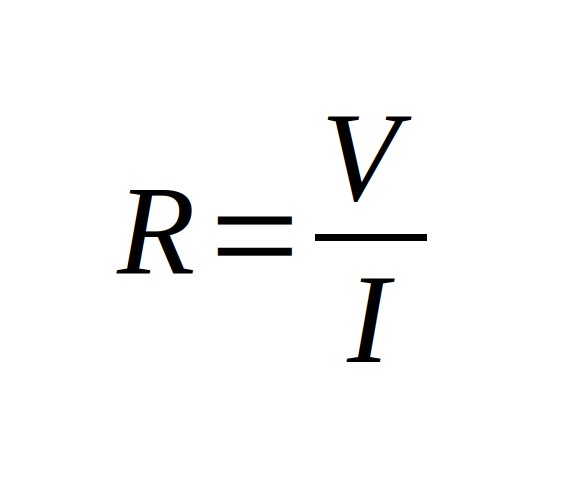
Where R is the electrical resistance, V is the voltage and I is the current, now let's try this rule in a very simple circuit, where we connect a 1 ohm resistor to a 1 Volt voltage source
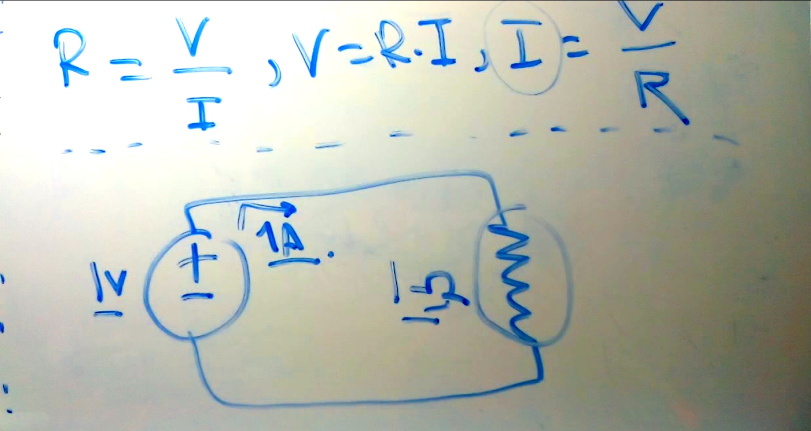
Here we have the voltage which is 1 Volts and we have the resistance which is 1 Ohm, yet we don't have the current, which we can easily calculate by flipping the rule a bit, so that I = V/R that mean that the current drawn by this 1 ohm resistor is equal to 1 Volt divided by 1 Ohm which is equal to 1 Ampere or 1000 milli Ampere (1000mA).
Now the voltage divider we'll use will consist of 2 resistors connected in series and hooked up to a voltage source like shown in this image
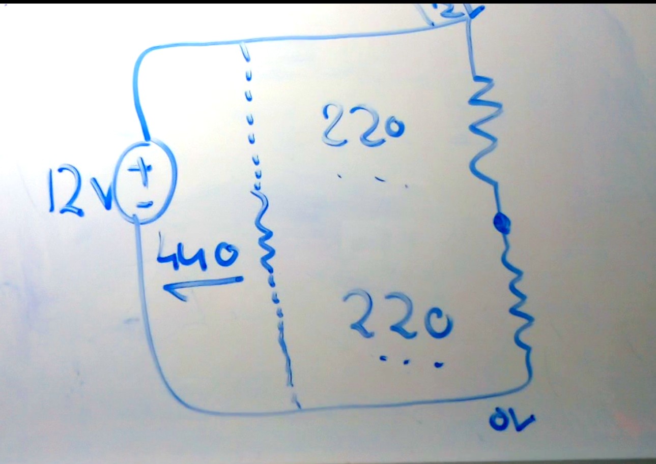
Now you will find that we have a new point in our circuit which is the point between the two resistors, this point will have our divided voltage, but we shall calculate the voltage at it, so we simply follow these simple rules:
- Imagine that the 2 resistors are one big resistor to calculate the current drawn by the two small resistors
- Calculate the current drawn by the big resistor
- calculate the voltage dropped by the first resistor connected to the positive terminal of the voltage source
This circuit has a 12 Volts voltage source, and two 220 ohms resistors connected in series and connected to the voltage source, our imaginary resistor will equal to 440 ohms, the current drawn by the two resistors will equal to Voltage divided by resistance, 12 / 440 which is equal to 0.027 Ampere or 27mA, now as we know the resistor 1 value (R1, the resistor connected to the positive terminal of the voltage source) and also known the current drawn by each resistors, which is equal and is 27mA we can calculate the voltage dropped by the resistor by finding the voltage by ohm's law! so V = I x R, 0.027 Amperes x 220 ohms which is equal to around 6 volts, thus the point we calculate the voltage for has a voltage of 12 volts (main voltage) subtracted by the dropped voltage by the resistor, 6 volts, so it will equal 12 - 6 = 6 volts! and congrats! we made a voltage divider, if you replaced the 12 volts voltage source by a 6 volts one for instance the output voltage at the point between the two resistors will equal to 3 volts!
Now you can replace the resistor values with ones that suites your needs, there is some examples below you can see, but keep in mind the that what matters is the ratio of resistance between the two resistors, so two 220 ohms resistors will act really like a 2200 ohms resistors, because what matters is the ratio and not the resistance of them in a voltage divider circuit.
Equation & Calculator
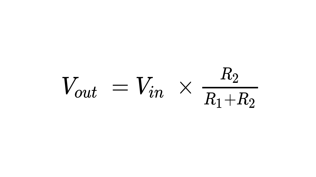
Really you don't do all of these calculations to know the output voltage of the voltage divider, there is a simple rule to calculate it and here it is! the input voltage (VIN) to the voltage divider is the voltage at the first resistor (R1) and the output voltage (VOUT) is of course is the voltage between the two resistors.
Here is a calculator you can easily use to calculate the output voltage of any two resistors voltage divider circuit.
Experiments
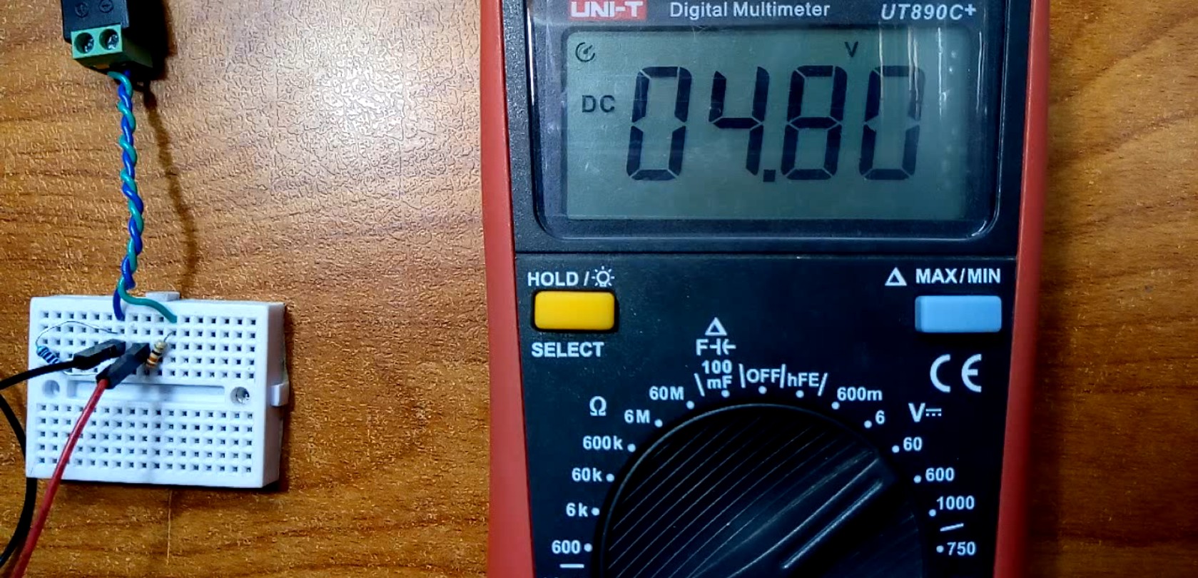
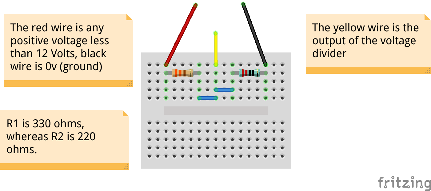
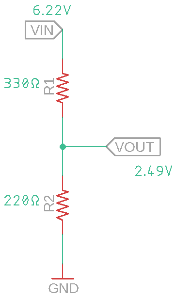
You can try this circuit yourself and test it, before using it with an Arduino, it uses value of 330 ohm for R1 and for R2 uses a value of 220 ohms, it should give an output of 4.8 Volts when the input is around 12 volts
But keep always in mind that voltage dividers are used mainly for voltage reference or for signal-related purpose and not for powering a motor or even an MCU or the voltage will drop quickly or even worse; if you use really low values like 10 ohms or so you might get something like this
really this isn't a real voltage divider, but just showing that it may explode or burn like this, probably you got the idea ....
Examples
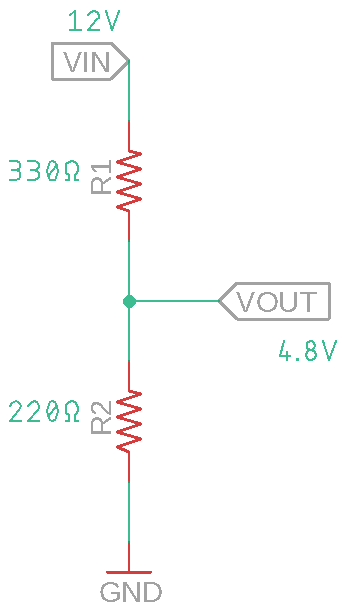
So this is an example of a voltage divider circuit which I will use with my Arduino pro mini to measure the high voltage, I set that the maximum voltage at the input will be 12 volt thus the maximum output voltage should be around 4.8 volts
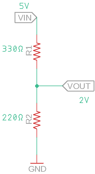
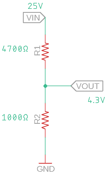
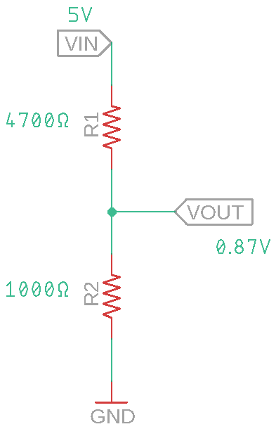
This is another examples using different values of the resistors.

Hooking to Arduino
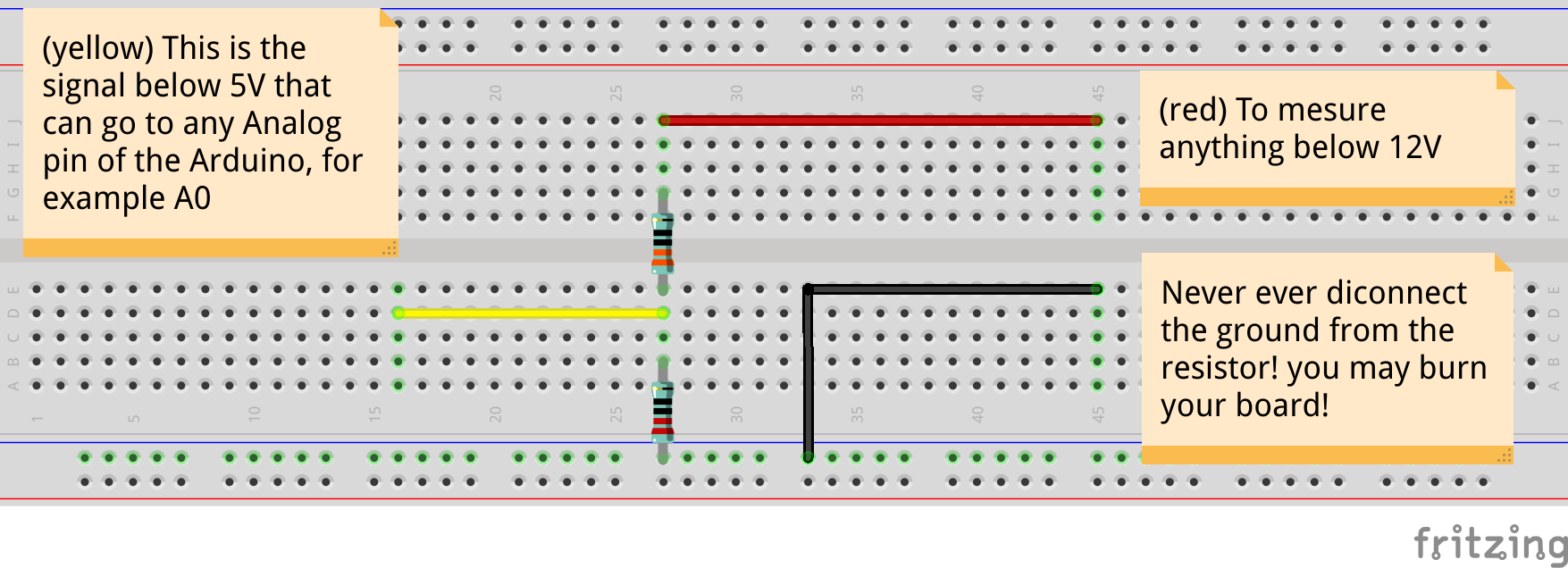
This is the circuit which uses r1 with a value of 330 and r2 with a value of 220, connect the yellow wire to any analog pin you have free on your Arduino board or any MCU, this circuit only works with Boards working at 5 volts, a 3.3 Volt version of the arduino pro mini will get fried by this circuit, you should probably find another resistors value.
Don't disconnect the resistor connecting to the ground while the circuit is working! ( see important points section )
Program
Detailed code
Now let's talk about our program, by now you should understand that actually the arduino is reading the divided voltage, so in order to get the main real voltage we should reverse the equation so we get the main input voltage we want to measure.
#define BAUD 9600 // Computer Serial speed
#define PIN A0 // Analog pin connected to the output of the voltage divider
These is the first line of code, here I define the BAUD as 9600 which will be used as the speed of serial communication so that we can see the results, and PIN is the analog pin connected to the output of the voltage divider.
const unsigned long r1 = 330;// the resistance of resistor 1 (R1) in "Ohms"
const unsigned long r2 = 220;// the resistance of resistor 2 (R2) in "Ohms"
const float sys_voltage = 4.91;// The voltage of the MCU, can be 3.3V, 5V or even as low as 1.8V!

float vout;// The output voltage from the resistor-divider (The voltage from the analoge pin)
float vin;// The true input voltage we want to mesure

int resoulotion = 1023; // ADC resoulotion, in arduinos UNO,Nano,Mini it's 1023
Here I declare r1 as the resistance in ohms for resistor 1, similary for r2, then the sys_voltage variable is used to store the operating voltage of the MCU, so if you are using an Arduino UNO for instance consider putting a value near 5V, maybe 4.9 maybe 5.2V so changing this makes the reading more accurate, vout and vin are variables to store the measured voltage of the arduino and the calculated real voltage we are measuring, lastly the resoulotion is the number of ADC steps present in your MCU board, for now 1023 is the value for ant ATMega328 based board like the Nano, Mini, and UNO, for the STM32 board "bluepill for instance" it's 4095.
void setup() {
  // put your setup code here, to run once:
  Serial.begin(BAUD);
}
Of course in the setup we just declare the Serial communication and it's speed.
void loop() {
  Serial.println(getVoltage());
  delay(100);
}
In the loop we print to the serial, to see on the computer, the calculated value returned by getVoltage() function.
float getVoltage(){
  // Here we calculate the voltage the Arduino reads,
  // which is the output voltage of the voltage divider
  int sensorValue = analogRead(PIN);
  float voltage = sensorValue * (sys_voltage / resoulotion);

  return calculate(r1, r2, voltage);
}
This is the getVoltage() function, the first part of it it calculate the voltage measured by the arduino, second part it returns the value returned by another function called calculate()
float calculate(unsigned long r_1, unsigned long r_2, float vout){
  /*
   The main rule is:
   Vout = Vin x (R2/R1+R2)

   the inverse of it:
   Vin = (Vout x (R1+R2)) / R2
  */
  return (vout*((float)r_1+(float)r_2) / (float)r_2);
}
Lastly, this is the calculate function, which just takes an output voltage, resistor1 value and resistor 2 value and claculates vin value, or the input voltage, through the reversed calculation.
Complete Code
visit github for complete project files: here